
3. Basics of vacuum
Important matters for the formation of thin films using vacuum are as described below.
3.1 What is vacuum?
What kind of state does vacuum refer to?
In the Japanese Industrial Standards (JIS), vacuum is defined as “the state of a specific space that is filled with a gas at a pressure lower than atmospheric pressure”. This means a thin-air state created by eliminating the air in a container in some way. In a vacuum that can be created on the earth, a large volume of gas still remains. For example, even in an extreme high vacuum of 10-12 Pa, approximately 105 gas molecules are remaining per liter. However, from the perspective that the gas exists in the order of 1022 molecules per liter under atmospheric pressure, this is a very small value.
3.2 Mean free path
Gases are aggregates of a lot of molecules that fly around freely.
Any type of gas whose atmospheric pressure is one at 0℃ consists of 6.02 x 10²³ molecules (Avogadro’s Number) per mol and accounts for a cubic volume of 22.4 L. Respective molecules fly around at an average velocity of approximately 500 – 1,500 m/s at room temperature, although it varies depending on the type. If flying molecules collide with each other, they change their flying direction and velocity and then collide again with other molecules repeatedly. Here, the average flying distance between collisions is called a mean free path, which is an important value for processes using vacuum.
There is a relationship between the mean free path λ [m], pressure P [Pa], Temperature T [K] and molecular diameter D [m] as follows:

In short,
- The mean free path is inversely proportionate to the pressure,
- The mean free path is proportionate to the temperature, and
- The mean free path is inversely proportionate to the square of the molecular diameter.
The relationship with the pressure is important; the mean free paths are approximately 7 mm at 1 Pa, 7 cm at 10-1 Pa, 70 cm at 10-2 Pa, 7 m at 10-3 Pa, and 70 m at 10-4 Pa in the air at 25℃.
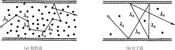
Figure 3.1 The conceptual diagrams of mean free paths 2)
Figure 3.1 shows the conceptual diagrams of mean free paths. Here, L [m] represents the typical dimensions of a subject system.
- λ≪L The state where a mean free path is short and gas molecules collide with each other frequently is called a viscos flow, and the CVD is a process that mainly uses this region. The viscos flow can be treated as a continuous gas in the same way as a liquid.
- λ≧L If a mean free path is as long as or longer than a container, gas molecules collide with the container wall more frequently than with other molecules. This state is called a molecular flow. Most of the PVD processes use this region.
3.3 Impingement rate
Another important concept is the number of gas molecules that collide with objects in the gas or container wall. This is called impingement rate Γ, which has the following relationship between the pressure P [Pa], molecular weight of the gas M, and temperature T [K]:

This value is proportionate to the pressure and is inversely proportionate to the square root of the molecular weight of the gas and the square root of the temperature [K]. At 10-4 Pa, which is the ultimate pressure of a general PVD process system, the impingement rate of oxygen at 25℃ is 2.72 x 10¹⁸ molecules/m2・s, and this is a very large value. As the number of atoms on a solid surface is approximately 1019 per square meter, this means that all the atoms on the surface are collided by oxygen molecules in several seconds and the surface is covered with them.
3.4 Gas flow
In order to exhaust the gas molecules in a vacuum container, it is necessary to give a flow in a certain direction to the gas molecules that move isotropically in their natural state.1)2)3)4)
Although gas flows can be treated equally as liquids and so on, a large difference is that gases are compressible while liquids and fluids are generally incompressible. Gas flows can first be classified into viscos flows and molecular flows.
-
Knudsen number
Mean free paths are inversely proportionate to molecular densities. As molecular densities are directly proportionate to pressures, mean free paths are inversely proportionate to pressures. Therefore, a mean free path becomes longer if the pressure decreases. The value Kn obtained by dividing the above-mentioned mean free path λ by the typical length of a vacuum system L is called a Knudsen number.
-
Viscous flow (Kn < 0.01)
In viscous flows, gas molecules collide with each other frequently in a space, and viscosity is generated as a mutual action between molecules. Viscous flows are characterized by occurring under high pressure conditions and an extremely short mean free path of gas molecules compared to the dimension of a system where a gas flows.
Viscous flows can be further classified into turbulent flows and laminar flows.
It can be determined whether a flow is turbulent or laminar by its Reynolds number Re. The Reynolds number is expressed by the fluid pressure p, average flow velocity v, flow tube diameter D, and viscosity coefficient of the fluid η.
An Re value smaller than 1,200 represents that the flow is laminar, a value larger than 2,300 represents that it is turbulent, and a value between 1,200 and 2,300 represents that it is intermediate.
2-1) Laminar flow (Re < 1,200)
If the flow velocity is low, the fluid velocity in a specific place is constant and does not fluctuate temporally, and a parallel flow line is formed along the tube wall that is the boundary of the fluid. This is called a laminar flow.2-2) Turbulent flow (Re > 2,300)
Even in the case of a fluid of the same substance, if the velocity becomes higher, the fluid velocity fluctuates temporally and spatially in an irregular way, and the flow line is not parallel to the tube wall and forms spirals. This is called a turbulent flow. The turbulent and laminar flows of liquids can be made visible easily by adding ink to fluids. And strong turbulent flows of gases can be made visible by adding smoke or mist to them.Table 3.1 Typical gas flows 1)
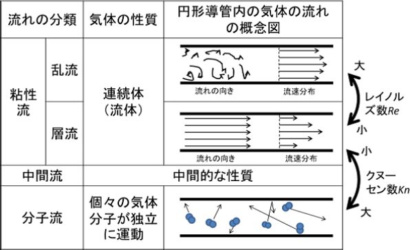
- Molecular flow (Kn > 0.3)
On the other hand, if the pressure is low, the gas molecules rarely collide with each other in a space and the mean free path of the gas molecules is extremely longer than the gas flow dimension, the flow is called a molecular flow. - Medium flow (0.01 < Kn < 0.3)
A flow between a viscous flow and a molecular flow is called a medium flow.
3.5 Heat conduction of vacuum
Three primary forms of heat transfer are as follows:7)
The physical quantities, Q: Heat transfer amount [W], A: Cross-section area [m2], q: Heat flux, T: Temperature [K], and x: Position [m], are defined.
- Heat conduction
(Heat transfer amount) ∝ (Temperature gradient)
- Heat transfer convection
(Heat transfer amount) ∝ (Temperature difference)
- Heat radiation(Heat Radiation)

If a vacuum is in the viscous flow region, the number of gas molecules that deliver thermal energy changes with a change in pressure. In this case, the mean free path also changes, and the molecular direction becomes random with respect to the heat conduction. As a result, the amount of heat transfer caused by a gas is independent of the pressure.
In the case where a vacuum is in the molecular flow region, if the mean free path becomes longer than the face intervals, the gas molecules that gained thermal energy move directly between the faces. Therefore, the amount of heat transfer caused by a gas is dependent on the number of gas molecules. As the number of gas molecules is proportionate to the pressure, the amount of heat transfer caused by gas is proportionate to the pressure. However, as the number of gas molecules that deliver thermal energy is small, the heat conduction becomes small. Forming a vacuum in the molecular flow region in the space between double containers makes the space almost heat insulated. Thermal containers utilizing this are widely used.
In the case of a medium flow, a convection needs to be taken into consideration.
3.6 Unit and region of vacuum
In the explanation above, Pa (Pascal) was used as a unit of vacuum.
In the SI unit system, the unit of pressure is converted as shown below.
In the past, a unit called Torr was used.
This unit was used in past literatures, and the corresponding value is as follows: 133.3 Pa = 1 Torr
And one atmosphere is 1,013 hPa (hectopascals) = 1.013 x 10⁵ Pa.
The vacuum region that is currently used is as wide as 15 digits at or below atmospheric pressure. The JIS classifies this region as follows:
Table 3.2 Range of vacuum and pressure
| Description | Pressure range |
|---|---|
| Low vacuum | Prevailing atmospheric pressure (31kPa to 110kPa) to 100Pa |
| Medium vacuum | <100Pa to 0.1Pa |
| High vacuum | <0.1Pa to 10-6Pa |
| Ultra-high vacuum | <10-6Pa to 10-9Pa |
| Extremely-high vacuum | below 10-9Pa |
In general, the PVD processes use high and ultra-high vacuum regions, and the CVD processes use low and medium vacuum regions.
3.7 Vacuum and thin film formation
With respect to the PVD, the reasons for forming thin films in a vacuum can be described as below.
- To elongate the mean free path to reduce the collision of the deposition material with the residual gas
To reduce the loss of thermal energy of the evaporation material as well as the reaction of the evaporation material with the residual gas - To reduce the rate of impingement of the residual gas on the substrate on which a thin film is formed
With respect to the CVD, a relatively simple vacuum exhaust system is sufficient, and a vacuum is used for the following purposes, because CVD does not require any vacuum:
- To reduce the residual gas in the reaction container and maintain the degree of purity of the raw material gas introduced
- To transport the raw material gas to the reaction container by using a pressure difference and diffuse the gas in the container homogeneously
- To put plasma into a depressurized state where it can be controlled easily, when a plasma is used for reaction
3.8 Creating a vacuum
3.8.1 Vacuum container
To create a vacuum, a container (chamber) for blocking out the outside air is necessary. This container needs to be made of a material with the strength, thermal resistance, corrosion resistance, and workability that are generally required for machinery, and also needs to satisfy the following properties as a vacuum container:
- The leakage and transmission of gases are less likely to occur
- The release of occluded gases is less likely to occur
- Gases are less likely to adsorb on the surface
- The vapor pressure of the material is low
- The surface is less likely to decompose, dissociate, and react
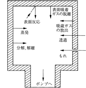
Figure 3.2 Potential gas generation in a vacuum system 1)
Figure 3.2 shows the generation sources of released gases in a vacuum system. For use in a vacuum, materials that are less likely to release gases due to these causes need to be selected. Although glass was used in the past, stainless steel or nickel-plated soft steel is generally used these days. Aluminum alloy is also sometimes used in ultra-high vacuum systems. Vacuum containers need to be made of these materials, and particular attention is required for their surface finish and welding.
As a vacuum system, it needs to be equipped with a vacuum pump, valve, and pipes for vacuum exhaust. In addition, the terminals for introducing the drive mechanisms, sensors, and power sources required for processes as well as the ports for internal monitoring need to be mounted. Gaskets are used for connecting such components, and they are made of synthetic rubbers such as Viton and nitrile. Furthermore, in ultra-high vacuum systems, copper gaskets are generally used because baking (heating for promoting gas release) is required to reduce gas release from structural materials as much as possible.
3.8.2 Vacuum pump
The gas in a vacuum container is discharged outside by a vacuum pump. However, no pump that can exhaust the gas from atmospheric pressure to high vacuum continuously is available.
Normally, the gas is exhausted in a sequential manner by a roughing exhaust system and high vacuum exhaust system, separately. Table 3.2 shows the operating pressure ranges of typical pumps.
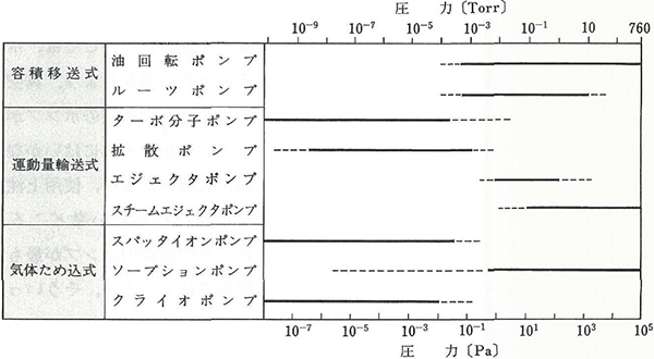
Figure 3.3 The operating pressure ranges of typical vacuum pumps 2)
(Note) These operating pressure ranges show general values. The range varies depending on the models.
- Roughing pump
This pump can continue to exhaust gas until the pressure reaches from atmospheric pressure to the region where a high vacuum pump is operable. In addition, it is used on the atmosphere side as an auxiliary pump for displacement type high vacuum pumps other than capture type pumps.- Oil-sealed rotary pump
This pump is typically used for roughing. As Figure 3.4 shows, this pump has a structure in which a rotor rotates to change the volume of the space sealed with oil while it rotates once and discharges the absorbed air. It can be classified into three types in terms of structure (rotary blade type, cam type, and vibrating piston type), but the pumps in the markets have made a lot of achievements. Therefore, it is not necessary to stick to these types from the viewpoint of users.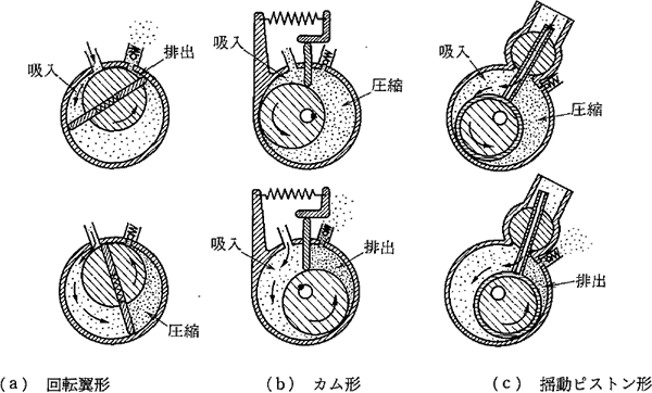
Figure 3.4 The structure and air exhaust method of oil-sealed rotary pumps 2)
- Roots vacuum pump
This pump is designed to rotate two rotors whose cross section is cocoon-shaped at high speeds (1,500 – 3,000 rpm) while keeping a narrow space (0.2 – 0.4 mm) to exhaust the gas. Although this pump is intended for roughing, it cannot be used at atmospheric pressure and needs to be used at a pressure of approximately 1,000 Pa. In general, this pump is used as a booster pump by being mounted between an oil-sealed rotary pump and a vacuum container and is extremely effective in shortening the roughing time. In addition, in processes where an ultimate pressure of approximately 0.1 Pa is sufficient, this pump enables the achievement of purposes without using high vacuum exhaust systems. - Dry pump
As oil-sealed rotary pumps are sealed with oil, there is a possibility that a tiny amount of oil could flow backwards into a vacuum container. This amount is so tiny that it does not become a problem in most processes, but it affects yields in semiconductor manufacturing processes where miniaturization has been promoted. In addition, in processes where a reactive gas is used, there is a possibility of problems occurring due to reaction with and deterioration of oil. Dry pumps have become widespread because of their ability to prevent such problems. Many types of structures have been developed, with the major ones being the roots type, claw type, screw type, scroll type, and turbo type.
- Oil-sealed rotary pump
- High vacuum pump
In the general PVD process, gas needs to be exhausted to the 10-4 Pa level as the background pressure, in order to reduce the effect of the residual gas. Therefore, the gas needs to be continuously exhausted using a high vacuum pump after roughing gas exhaustion. In addition, the gas exhaustion also needs to be continued even during film formation to keep high vacuum.
The high vacuum pumps affect film quality significantly.
The characteristics of the three types of high vacuum pumps that are generally used in mass production at present are as described below.- Diffusion pump
This pump has been used from long ago and is also used currently. Figure 3.5 shows the principal diagram.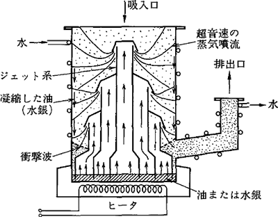
Figure 3.5 The principal diagram of a diffusion pump 2)
Diffusion pumps are characterized by less instances of failure because of their design with no drive member, as well as their moderate price compared to other high vacuum pumps. The precautions for using diffusion pumps are as follows:
1) Avoid interrupting the flow of cooling water during operation
2) Avoid exposing them to the atmosphere while hot, in order to prevent them from being deteriorated due to the oxidation of their operating oilThere is a possibility that a tiny amount of oil could flow backwards into the vacuum chamber because oil vapor is utilized. However, it does not become a problem in most applications because the operating oil is improved and the baffle is well designed. In addition, the velocity of discharging water, which accounts for a large portion of residual gas, is not so high when exhausting the gas to from a high vacuum. Therefore, in many cases, a liquid nitrogen trap or a cold trap of approximately between – 100 and – 140℃ is used together to discharge water.
- Cryopump
As Figure 3.6 shows, a cryopump is equipped with two types of panels that are cooled at approximately 80 K and 20 K or lower as well as an activated charcoal on its second panel. Figure 3.7 shows the vapor pressure curves relative to the gas temperatures. The vapor pressure becomes very low when the gas becomes low in temperature. Therefore, the gas condenses and adsorbs onto the 80 K and 20 K panels. In addition, even on the 20 K panel, gas with high vapor pressure adsorbs onto the activated charcoal.
This is the exhaust principle of the cryopumps, which are capture type pumps. Therefore, a reconditioning process is required in regular cycles. The features of cryopumps are as follows:
1) Enables the formation of a clean vacuum with no oil content
2) The water discharge velocity is very high (approximately three times higher than the air exhaust velocity)
3) The velocity of discharging hydrogen, generated during the processes, is highBecause of the features described above, it is very effective to use a cryopump in the formation of optical thin films or plasma processes utilizing oxygen. However, since oxygen and ozone are captured in the cryopump, it is necessary to take safety measures against oxygen and ozone in the reconditioning process.
Additionally, safety measures are complicated because other measures including responses to abnormalities also need to be taken.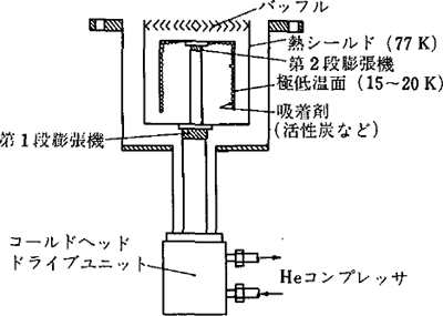
Figure 3.6 The conceptual diagram of a cryopump 2)
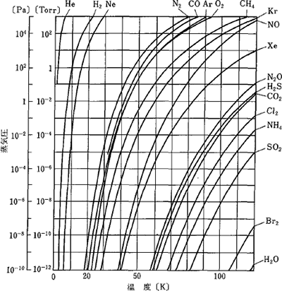
Figure 3.7 The vapor pressure curves of gases 2)
- Turbo molecular pump
As Figure 3.8 shows, a turbo molecular pump consists of a rotator (or rotor, rotating blade) and a stator. The peripheral velocity of the rotator that rotates at high speeds (14,000 – 90,000 rpm) is equivalent to the flight velocity of gas molecules, which is high enough to flick gas molecules away in an effective manner.
The advantages and disadvantages of turbo molecular pumps are as shown below.
Advantages- They can be operated continuously for a long time, unlike gas capture type pumps
- The heavier the molecules are, the higher the compression ratio and exhaust velocity become
- Short start-up time compared to other pumps
- Flexible in the mounting direction in the case of magnetic suspension type
- Low compression ratio and exhaust velocity for light gases such as hydrogen and helium
- Because they have a structure that rotates at high speeds, they sometimes crash due to the damage to the rotator and stator. The damage occurs not only when foreign matter enters but also when the atmospheric pressure is introduced from the air inlet or the exhaust side. Therefore, the mounting structure needs to be considered as a countermeasure.
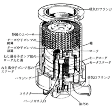
Figure 3.8 The structure of a turbo molecular pump 3)
- Other pumps
Ultra-high vacuum systems such as Molecular Beam Epitaxy (MBE) systems sometimes use sputtering ion pumps. These pumps exhaust gas by incorporating the gas into a titanium thin film, formed by sputtering, through the getter action, and their ultimate pressure is 10-8 – 10-9 Pa.In addition, the liquid nitrogen traps that are frequently used and the freezing traps at −100℃ or lower serve as the discharge pumps for water. As most of the residual gas is water in the high vacuum region, they are highly effective in shortening the time required for the gas exhaust process.
- Diffusion pump
- Vacuum exhaust system
Figure 3.9 shows general high vacuum exhaust system diagrams, and Figure 3.10 shows the vacuum exhaust process (time – pressure).
In this system, a roughing exhaust system and a high vacuum exhaust system are combined.
In the general gas exhaust procedure in the case of Figure 3.8 (a), the gas is exhausted to create a high vacuum according to the following procedures while the roughing pump and high vacuum pump are operated.- Exhaust the gas from the vacuum chamber with only the roughing valve opened
- When the pressure reaches approximately 1 Pa, close the roughing valve and then open the auxiliary valve
- After a few seconds, open the main valve, reduce the pressure to the intended vacuum pressure, and initiate the process
- After completing the process, close the main valve
- Open the leak valve to introduce atmospheric air into the vacuum chamber, and release it when the pressure reaches atmospheric pressure
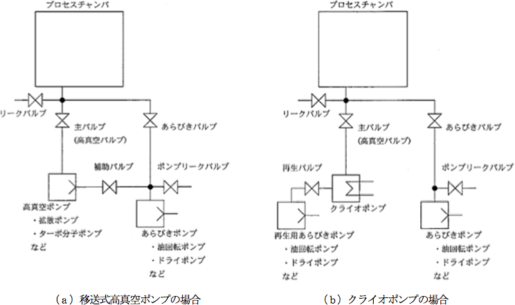
Figure 3.9 General high vacuum exhaust system diagram
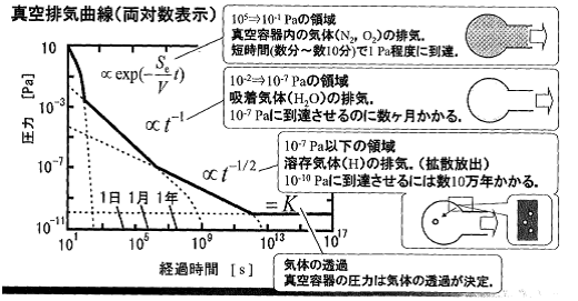
Figure 3.10 Vacuum exhaust process 6)
At present, exhaust processes like this are performed automatically in almost all systems.
In addition, the systems are also designed to reject incorrect operation by using an interlock, when operating the systems manually in the event of a problem. However, attention needs to be paid to avoid introducing the atmospheric air into high vacuum pumps.
3.9 How to measure a vacuum
In processes utilizing a vacuum, the control of vacuum pressure influences the entire process stability and, as a consequence, also affects the product yield. In addition, depending on the process, the residual gas in a vacuum and partial pressure during the process need to be controlled.
The vacuum gauges that are generally used are classified into total pressure vacuum gauges that measure the total vacuum pressure regardless of the type of residual gas and partial pressure vacuum gauges that measure the partial pressure of each type of gas.
Table 3.3 The measurement ranges of typical total pressure vacuum gauges
| Type of total pressure vacuum gauge | Pressure measurement range (Pa) |
|---|---|
| Pirani gauge | 104 – 10-1 |
| Capacitance manometer | Atmospheric pressure (105) – 10-2 |
| B-A type hot cathode ionization gauge | 10-1 – 10-6 |
| Penning type cold cathode ionization gauge | 1 – 10-3 |
| Spinning rotor gauge | 1 – 10-4 |
(Note) Many vacuum gauges that are actually sold in the markets cover only a part of these measurement ranges. When selecting a gauge, it is necessary to check the measurement range of each model.
3.9.1 Total pressure vacuum gauge
Table 3.2 shows typical total pressure vacuum gauges and their measurement ranges.
- Pirani gauge
This vacuum gauge measures the change in the temperature of a heated thin metallic wire as a change in electric resistance, by utilizing the fact that the heat conduction of low-pressure gas is dependent on the gas pressure. This gauge is frequently used for the measurement of medium vacuum (100 Pa – 0.1 Pa). Figure 3.11 shows an example of the gauge head.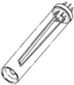
Figure 3.11 A gauge head of a Pirani gauge 1)
- Diaphragm gauge
This vacuum gauge reads the elastic deformation of a diaphragm due to pressure difference mechanically and electrically. The type of diaphragm gauge that is greatly used is the capacitance manometer that measures a change in the distance between a diaphragm and an opposed electrode as a change in the electrostatic capacity and then converts it into a change in pressure. It is used in the region between atmospheric pressure and medium vacuum. Figure 3.12 shows a structural example of a gauge head.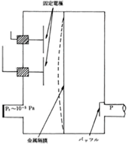
Figure 3.12 A gauge head of a capacitance manometer
- Hot cathode ionization gauge
This vacuum gauge determines pressure by ionizing a gas with the emitted electrons through the use of a hot filament as a cathode and then measuring the ionic current. Figure 3.13 shows a gauge head of a triode type ionization gauge.
In general, B-A is the most common type of hot cathode ionization gauge. It is called this because the gauge head of this type of vacuum gauge is designed as shown in Figure 3.14, and it was developed by Bayard and Alpert. In addition, it is characterized by having a structure in which a hot cathode is placed outside the cylindrical grid and an ion collector electrode made of thin wire is placed on the central axis, as well as by the photoelectric current reduced by soft X-ray to expand the measurement limit. This is the total pressure vacuum gauge that is used most frequently in vacuum systems utilizing high or ultra-high vacuum.
As the hot filament of a hot cathode ionization gauge burns out if it is used in a low vacuum, regardless of type, its application is limited to use in a high or ultra-high vacuum. Careful attention needs to be paid when turning the hot filament on and off when using this vacuum gauge with no interlock, such as when it is added to a vacuum system later.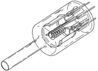
Figure 3.13 A gauge head of a triode type ionization gauge 1)
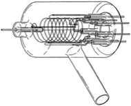
Figure 3.14 A gauge head of a B-A type hot cathode ionization gauge 1)
- Cold cathode ionization gauge
This is an ionization gauge that utilizes a magnetic field to promote the ionization of gas without using any hot filament. The typical type is the Penning gauge designed by Penning, and Figure 3.15 shows its electrode structure.
– A circular anode is placed between a pair of parallel plate cathodes, and a magnetic field is applied using a permanent magnet in parallel with their axes
– An ionic current is measured after increasing the ionization probability by applying a magnetic field
– The ionic current is converted into pressure
As a cold cathode is used, this gauge does not cause filament burn-out and has a long life. In addition, its measurable range is from medium vacuum to high vacuum. Therefore, it is frequently used in some processes because it is easy to use. However, the measurement accuracy is not so high.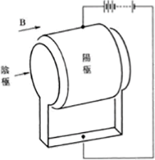
Figure 3.15 The structure of the electrode of a Penning type ionization gauge
- Spinning rotor vacuum gauge
Figure 3.16 shows the structure of the gauge head. The measurement principle of this vacuum gauge is that the pressure is determined by measuring the attenuation of the rotation frequency of a steel ball, which is floated by a magnetic field in a space and rotated due to the viscous resistance of the gas. As this vacuum gauge achieves high measurement accuracy and the pressure is determined based on the measurement of a basic physical amount, this vacuum gauge is used as a standard or substandard of vacuum pressure. However, this vacuum gauge is not suitable for use in the processes, because it takes time to perform measurement and cannot perform in-situ measurement.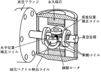
Figure 3.16 The gauge head of a spring rotor vacuum gauge 2)
3.9.2 Partial pressure vacuum gauge
This vacuum gauge measures the composition of the residual gas as partial pressure of each type of gas, by ionizing the gas in a vacuum and separating the produced ions using an electric field created by four columnar electrodes placed in parallel. It is also called a mass filter.
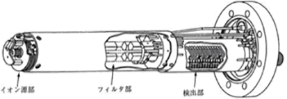
Figure 3.17 The structure of the analyzer tube of a quadrupolar type mass spectrometer 1)
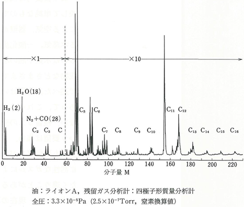
Figure 3.18 A measurement example of a quadrupolar mass spectrometer 2)
Figure 3.18 shows a measurement example. The method of decomposing organic matter with a large mass to be used when ionizing them needs to be identified by estimating it based on the measurement example.
3.10 References
- Edited by Japan Vacuum Industry Association: Learning the Elements of Vacuum Technology, Kogyo Chosakai Publishing Co., Ltd. (1999)
- Katsuya Nakayama: Readings from the Practices of Vacuum Technology; New Edition, page 32, Ohmsha, Ltd. (1994)
- Osaka Vacuum, Ltd.: Catalogue
- Edited by Technology of Vacuum Editorial Committee: Technology of Vacuum, page 157, Industrial Technology Service Center (1990)
- The Optical Thin-Film Science and Engineering Group: The Early Days of Optical Coatings and Vacuum Technologies in Japan (2014)
- Japan Vacuum Industry Association: The 21st Vacuum Technology Workshop, Vacuum Walking Course (2015)
- Yutaka Abe: Notes of the First Lecture on Heat Transfer Engineering http://www.kz.tsukuba.ac.jp/~abe/
- Yasuhiko Senda: Theoretical Analysis of Vacuum Evacuation in Viscous Flow and Its Applications, SEI Technical Review, No. 176 (2010)
- Hajime Yoshida, Tomoko Itakura: Analysis of Gas Flow in Vacuum and Pressure Reduction Processes, The 63rd Japan Society of Applied Physics Spring Meeting (2016)