


4. Plasma
In a vacuum, that is, in a reduced pressure state, the discharge phenomenon of a gas is very important. In all thin film formation processes other than the vacuum deposition, the plasma generated by the discharge phenomenon of a gas is utilized.
In fact, as plasma phenomena are very complicated, many specialized books giving a detailed explanation on them are published. Here, the outline of plasma phenomena is explained in a very simple manner.
4.1 Reaction in a plasma
As the processes of the excitation and ionization of the electrons or molecules in a plasma, the following reactions are presumed:1)12)
The probabilities of these reactions are represented by the cross-section areas with respect to each reaction process.
Described below are major reaction processes, expressing an electron as e(-1 valence) and gas molecules as A, B and M.
4.1.1 Excitation and ionization
- Excitation and ionization caused by electron collision
- Excitation
A + e → A* + e
AB + e → AB* + e - Dissociation
AB + e → A + B + e - Direct ionization
A + e → A+ + 2e
AB + e → AB+ + 2e - Cumulative ionization
A* + e → A+ + 2e
AB* + e → AB+ + 2e - Dissociative ionization
AB + e → A+ + B + 2e
- Excitation
- Excitation and ionization caused by ion or neutral particle collision
- Thermal ionization
When the gas temperature becomes high, the kinetic energy of neutral particles increases and the neutral fast particles that cause ionization in the event of a collision are generated. - Penning ionization
A + B* → A* + e + B - Ionization caused by a collision between excited particles
A* + B* → A+ + e + B
- Thermal ionization
- Photoexcitation and photoionization
If a gas is irradiated with monochromatic light to change its energy (wavelength), absorption occurs at a specific wavelength and the gas is excited or ionized.
4.1.2 Recombination
- Ion-electron recombination
- Radiative recombination
A+ + e → A* + hv - Dielectronic recombination
A+ + e → A*
A* → A** + hv
A* + B* → A** + B - Dissociative recombination
AB+ + e → A* + B* - Three-body recombination
A+ + e + e → A + e
A+ + e + B → A + B
- Radiative recombination
- Ion-ion recombination
- Radiative recombination
A+ + B– → AB + hv - Charge exchange recombination
A+ + B– → A* + B* - Three-body recombination
A+ + B– + M → AB + M
- Radiative recombination
- Reaction caused by negative ions2, 3 ,4, 5, 6)
The formability of negative ions is expressed by electron affinity. In other words, the higher the electron affinity is, the easier the atoms and molecules can form negative ions.
If a dielectric body undergoes reactive sputtering, the negative ions irradiated onto a substrate affect the crystallizability of the thin film significantly.
4.2 Discharge inception voltage
4.2.1 Direct electric field
Paschen discovered experimentally that the voltage Vs at which a dielectric breakdown occurs in a gas is the function of the product (pd) of the gas pressure (p) and gap length (d)8), and the following relational expression was obtained1) through Townsend’s experiment later9)10).1)
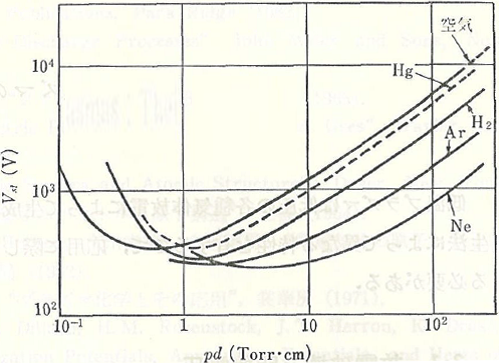
Figure 4.1 The Paschen curves of various types of gases 1)

Here, B and K can be treated as constants. The point of the minimum value of this V-shaped curve is called Paschen Minimum.
Assuming that the pressure is constant in the right side of pd at this point, Vs is almost proportionate to the electrode gap length. In the dielectric breakdown of a gas, the collision process of electrons and gas molecules dominates the phenomenon. Therefore, the dielectric breakdown voltage can be estimated using the above expression as long as the gas type, pressure, and gap length are determined.
On the other hand, in the left side of the Paschen curve, as the gap length becomes shorter if the gas pressure is constant. And before the numbers of electrons and ions increase in the space between the electrodes, their charged particles reach the opposed electrode. Therefore, a dielectric breakdown becomes less likely to occur, and Vs increases. In addition, if the gap length is constant, as the number of times of collision decreases with a decrease in the gas pressure, Vs increases.
4.2.2 High frequency electric field
In a high frequency electric field, the inception voltage is affected by pd in the direct electric field as well as the frequency of applied high-frequency wave. Figure 4.2 shows the frequency dependence of the inception voltage when pd is approximately 1 Torr・cm.
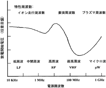
Figure 4.2 The frequency dependence of the discharge inception voltage related to the air 12)
The characteristics of each region in Figure 4.2 are as follows:
- Region I
- The low-frequency region is broadly similar to the direct electric field.
- Region II
- In the intermediate-frequency region, ions become less able to cope with the change in electric field and stay in the discharge space. Therefore, the number of ions that impact a cathode decreases and the inception voltage increases (A generally-used RF plasma of 13.56 MHz falls under this category).
- Region III
- In the high-frequency region, the electrons start to be trapped in the discharge space and collide with the gas molecules to ionize them frequently. Therefore, the inception voltage decreases rapidly.
- Region IV
- In the higher-frequency region, the phase of the electron transfer rate delays as compared to the phase of the electric field due to the completion of electrons, and the electrons become less able to obtain the energy required for ionizing the gas molecules from the electric field. For this reason, the inception voltage increases gradually.
4.3 Direct-current discharge plasma (Glow discharge)
For glow discharge, an electric discharge tube made by placing two metallic electrodes facing each other in a glass tube is used. A glow discharge can be generated by applying a direct-current voltage to both electrodes when the pressure inside the tube is 0.1 – 10 Torr. Figure 4.3 shows the light-emitting and dark spaces during a glow discharge.
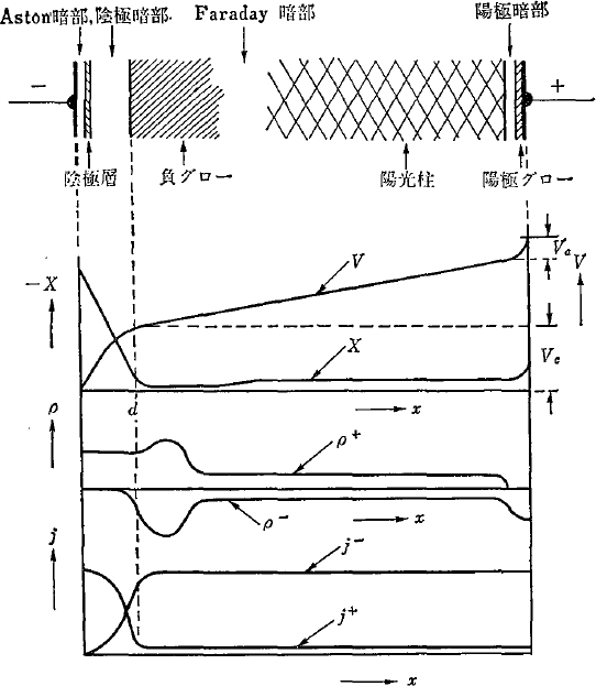
Figure 4.3 The potential V, electric field X, space-charge density ρ, and current density j during a direct-current discharge 1)
Figure 4.3 shows the potential distribution in the tube length direction during the discharge. As a steep potential gradient occurs near the cathode, the gas ions are accelerated drastically and collide with the cathode. Sputtering, as described later, utilizes this phenomenon to form thin films. The energy of monovalent ions and electrons accelerated at one volt is expressed as one electron volt (eV). One electron volt is equivalent to approximately 10,000 degrees in temperature.
The potential distribution shown as V in Figure 4.3 is in the case of a glow discharge that occurs when two metallic electrodes are equal in size and the distance between the electrodes is sufficient for the electrode size. However, in actual systems, the distance between the electrodes is often insufficient for the electrodes, and the anode (earth) is larger than the cathode. Figure 4.4 shows the potential distribution that occurs in such a case.
Looking at the light-emitting space, the dark spaces of the cathode and anode contact the electrodes, the positive column is shorter, and there are no Faraday dark spaces, leading to negative glow. The potential rises drastically at the cathode and is constant at the light-emitting space. This potential is called plasma potential Vs. The difference from Figure 4.3 is that the plasma potential has a positive potential with respect to the anode potential.
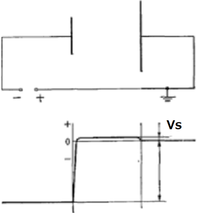
Figure 4.4 The potential distribution of glow discharge in a system 1)
If a plasma contacts solids such as vacuum containers, electrodes, and substrates, a space-charge layer called sheath is formed on their surface as shown in Figure 4.5.
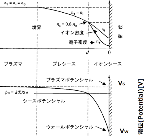
Figure 4.5 The potential distribution in a sheath 12)
In general, as the electron temperature of plasma is higher than ionic temperature, the potential of a solid surface becomes negative with respect to the plasma because of light and fast electrons, as shown in Figure 4.5. This potential, formed according to Poisson’s equation, not only accelerates the ions but also decelerates or reflets the electrons. Therefore, in this space-charge layer, an ion sheath in which there are too many ions is formed. In other words, in order to maintain the electric neutrality inside the plasma, an electric field, where the current density of negative charges including electrons and ions becomes equivalent to the current density of positive ions, is formed in the ion sheath (that is several times thicker than the Debye length) to accelerate the ions.
4.4 High-frequency discharge plasmas
High-frequency discharge plasmas are roughly classified into parallel plate type (capacitive coupling type) and coil type (inductive coupling type). Figures 4.6 (a) and 4.6 (b) show the schematic diagrams of the capacitive and inductive coupling types, respectively.
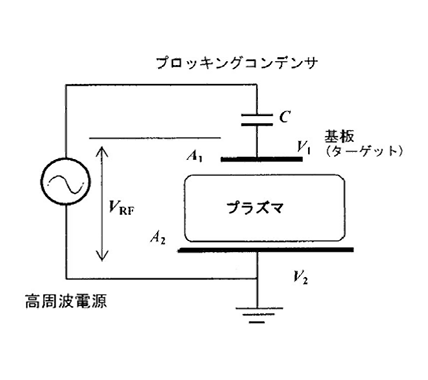
(a) Capacitive Coupling Plasma (CCP)
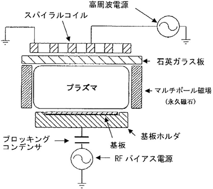
(b) Inductive Coupling Plasma (ICP)
Figure 4.6 High-frequency discharge plasmas 12)
4.4.1 Capacitive coupling plasma
When generating plasma using the system as shown in Figure 4.6 (a), the electrons and ions come flying toward the substrate (target) first12). However, as the average velocity of the electrons (up to 106 m/s) is much higher than that of the ions (up to 104 m/s), the electronic current of the electrons is much larger than the ionic current. However, negative electrical charges accumulate on the substrate surface and the substrate is biased to negative potential with respect to the plasma. Therefore, the electrons not only come to be turned away but also attract the ions (Refer to Figure 4.5.). Additionally, they come to equilibrium at the potential where the electronic and ionic currents become equal. The negative direct-current component of the potential of the substrate at this point is called self-bias Vdc. This voltage is generated only when the substrate is in the electrical floating state (when a blocking capacitor is connected as shown in Figure 4.6 [a]). On the other hand, as the potential Vs of the plasma becomes positive with respect to the substrate and vacuum container, the voltage of (Vs + Vdc) = Vw is applied to the ion sheath formed on the surface, and the impact of the ions accelerated at this voltage is given to the substrate.
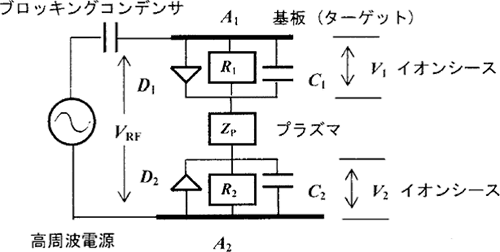
Figure 4.7 An equivalent circuit of a capacitive coupling plasma 12)
The equivalent circuit of Figure 4.6 (a) is as shown in Figure 4.7. Here, C1 and C2 are the electrostatic capacitances of the sheath, R1 and R2 are the direct-current resistances of the sheath, D1 and D2 are the diodes, and ZP is the impedance of the plasma. The ion sheath formed at the border between the plasma and the electrode passes an electric current only in one direction, so it becomes equivalent to the diodes. In addition, as the plasma is a good conductor, most of the high-frequency electric field is considered to be applied to the capacity of the ion sheath that is in series with the plasma. Therefore, the electric field generated in the discharge shaft direction is applied to the sheath, and the direct-current voltage (self-bias voltage) is applied to the sheath due to the rectification (diodes) between the plasma and the sheath. This voltage is proportionate to the high-frequency voltage applied to the sheath.
Therefore, as the time constants C1, R1, C2, and R2 are generally great enough compared to the high-frequency period, the voltages V1 and V2 that are generated at C1 and C2 are calculated as follows, when ZP is ignored and the maximum amplitude of the high-frequency voltage is VRF:

On the other hand, if the electrode area is A and sheath thickness is d, the sheath capacity C is calculated by C = A/d. Therefore, the following equation holds based on the above equation:

If the densities of the ion currents flowing through both electrodes are equal and the collision in the sheath is ignored, the below equation holds based on V∝d4/3 in Child-Langmuir’s space-charge limited current equation (26).

This equation proves that a high voltage is applied to small electrodes (substrates or targets), and as a result, the impact of ions is given to them.
4.4.2 Inductive coupling plasma
Figure 4.6 (b) shows the basic configuration diagram of an inductive coupling type system.12) If high-frequency (generally 13.56 MHz) current J is supplied to a coil, the magnetic field B is induced around the coil according to Maxwell’s formula (μ0: The magnetic permeability in a vacuum).

If this magnetic field changes over time, the electric field E is generated to counteract this magnetic field (Lenz’s law) and accelerates the ions. The ions accelerated by this induction field collide with gas molecules to generate and maintain a plasma. The high-frequency electromagnetic field penetrates into the plasma while decreasing in an exponential manner due to the skin effect of the plasma. If the distance at which the electric field intensity becomes 1/e (e: base of natural logarithm) is referred to as skin thickness and the plasma angular frequency of the plasma is much greater than the angular frequency of the high frequency wave (high density), the skin thickness is expressed by the value obtained by dividing the velocity of light by the plasma angular frequency.
4.5 References
- Mitsuharu Konuma, The Basics of Plasma and Film Formation, Nikkan Kogyo Shimbun, Ltd. (1985)
- Akira Kinbara, et al., Thin Film Formation and Control Technology through Sputtering Mainly in the Opto-Electronics Field, Technical Information Institute Co., Ltd. (2006)
- K. Ishibashi, K. Hirata, and N. Hosokawa, J. Vac. Sci. Technol., A10, (4) (1992)
- J. J. Cuomo, R. J. Gambino, and R. Rosenberg, J. Vac. Sci. Technol., 11 (1974)
- Y. Shintani, K. Nakanishi, T. Takawaki, and O. Tada, Jpn. J. Appl. Phys., 14 (1975)
- J. M. E. Happer, J. J. Cuomo, R. J. Gambino, H. R. Kahfman and R. S. Robinson, J. Vac. Sci. Technol., 15 (1978)
- Shinichi Kobayashi, Discharge Phenomenon in Vacuum, J. Vac. Soc. Jpn., Vol. 56, No. 1 (2013)
- F. Paschen: Annalen der Physik und Chemie, 5 (1989) 69
- J. S. Townsend, Nature, 62 (1900) 340.
- J. S. Townsend, Phil. Mag. S. 6, 1 (1901) 198 in 12, p. 27
- B. Chapman, Glow Discharge Process, John Wiley and Sons, New York (1980)
- Yukio Okamoto, The Basics of Plasma, J. Vac. Soc. Jpn., Vol. 59, No. 7 (2016)
5. Various film forming technologies based on the Physical Vapor Deposition (PVD) method