6. Actual PVD systems
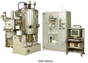
Figure 6.1 A batch type vacuum deposition system 17)
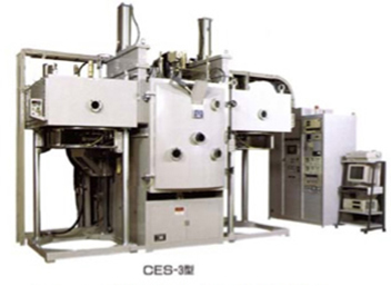
Figure 6.2 A continuous type vacuum deposition system 17)
In terms of the substrate processing method, the system configuration can be classified into the batch processing method as shown in Figure 6.1 and the continuous processing method as shown in Figure 6.2.
In the batch processing method, the following cycle is performed in a vacuum chamber: Placement of a substrate -> gas exhaustion and substrate heating -> film formation -> substrate cooling -> pressure release -> substrate retrieval.
In the continuous processing method, a substrate supply chamber and substrate retrieval chamber are provided in addition to a film forming chamber, and the film forming chamber is separated by a dividing valve such as a gate valve. This method is characterized by high productivity, because the substrates can be supplied without exposing the film forming process chamber to atmosphere. Below are the important composing elements of film forming systems.
6.1 Vacuum chamber
As mentioned above, the structural materials for the vacuum chamber must release or pass as little gas as possible. Although glass was used in the past, stainless steel or nickel-plated soft steel is currently used in general.
6.2 Vacuum exhaust system
In film forming systems, a roughing exhaust system and a high vacuum exhaust system are used in combination. These systems are designed based on the type and exhaust velocity of suitable pumps, according to the properties of materials to be processed, characteristics required for thin films, amount of throughput, and so on.
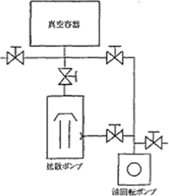
Figure 6.3 The system diagram of a high vacuum exhaust system 1)
Figure 6.3 shows the system diagram of a typical vacuum exhaust system. Even if the diffusion pump shown in Figure 6.3 is replaced with a cryopump or turbo molecular pump, the system diagram does not change. However, as the cryopump is a capture pump, the operation of the valve located at the back of the diffusion pump in the figure differs. In other words, if the cryopump is used, it needs to be regenerated after exhausting the gas whose volume is dependent on the pump’s gas capture limit.
Various principals are applied to vacuum pumps, and the pressure region in which they operate effectively is limited by such principals. Figure 6.4 shows the S-P curves representing the relationship between the exhaust velocity S [m3/s] and the pressure p [Pa] of various types of pumps.
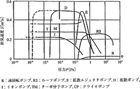
Figure 6.4 The S-P curves of various types of vacuum pumps 1)
6.3 Substrate holder
Substrates need to be moved in various ways depending on their shapes, in order to uniformize film quality and thickness. In systems that form films on lenses and wafers through vaporization, a dome-shaped holder is rotated or is made to rotate like a planet. In the systems that form films through sputtering, a method that rotates a flat plate holder or a carousel is often used. In addition, in the in-line type continuous systems, a passing film formation method using a tray is employed.
6.4 Film thickness gauge
While forming a film, it is necessary to monitor it using a film thickness gauge in order to verify that film with a desired thickness has adhered. In vacuum chambers, a quartz type or an optical type film thickness gauge is installed.
For optical thin films, optical type film thickness gauges utilizing the optical interference phenomenon achieve superior film quality control and film thickness reproduction. In sputtering, film thickness is controlled by the time-control method.
6.5 Gas introduction mechanism
When forming a film, gas needs to be introduced where appropriate. For the gas introduction, a method that continues supplying gas at a constant flow rate with a Mass Flow Controller (MFC) or a method that varies the gas flow rate to maintain a constant pressure with an Automatic Pressure Controller (APC) is used.
6.6 Substrate heating mechanism
If the substrate is heat-resistant, heating it during film formation enables the enhancement of its adhesion and properties. For heaters, filament materials such as nichrome, tungsten, and graphite, as well as light sources such as halogen lamp are used.
6.7 Control system for film forming systems
With the advancement and widespread use of computers, computer-based automatic control has become the general control method for film forming systems. In addition, automatic control has enabled strict and easy execution of various film forming parameters, eliminated human errors, and significantly enhanced reproducibility.
7. Various film forming technologies and systems based on the Chemical Vapor Deposition (CVD) method